CONTENTS
A) I. Main Characteristics & Application
11. Technical Data
III.Design & Function
I. Main Characteristics & Application:
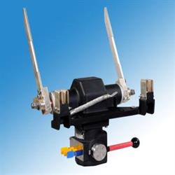
The two poles Earthing Switch shall be used to earth the circuits on both sides
of the air operated Main Circuit Breaker of Electric Locomotive, to ensure the
safety of the drivers of locomotive and workshop personnel safety during
checking and fault finding operations.
The Upper Casing of the Earthing Switch shall be mounted on the roof of the
traction vehicle, houses the Main Shaft on which the two break blades are
fitted. To make the earth connection, these blades establish the contact
between the frame and electric circuits on both sides of the air operated
Main Circuit Breaker.
The Lower Casing which houses the operating and interalia locking mechanism
of the Earth Isolating Switch shall be installed inside the traction vehicle.
The Earthing Switch is distinguished by the following features :
· Compact Design
· Rugged Construction
• Minimum Maintenance Requirements
• Reliable Operation Under Difficult Traction Operation
11. Technical Data:
Rated Voltage
Rated Current |
25 kV ac
400 A
|
|
Poles
Place of Mounting
|
2
Roof
|
|
Weight |
26 Kg.(Approx.) |
|
The Operating Lever of the Earthing Switch .. is connected through the arrangement
of uniball joint to the Main Shaft. Two Isolator Blades are fitted on the both sides
of the Shaft. The Operating Lever mechanism is kept in the Lower Casing of the
Switch.The Main Shaft along with the Blades are kept in the Upper Casing.
Both Upper & Lower casing are fitted with the Bolts. At the earthing position,
these Blades establish the contact between the frame and electric circuits on
both sides of the air operated Main Circuit Breaker. The Earthing Switch is fitted
on the roof, the upper portion(Upper Casing) is projected on the roof and the
lower portion (Lower Casing) is inside the machine room. Operator/Driver
can operate the switch by operating the interlocking arrangement from the
machine room through operating lever.
|