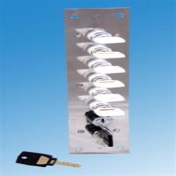
USE OF KEY MULTIPLIER SYSTEM IN WAG 9 LOCOMOTIVE
To guarantee the electrical grounding of the vehicle, with respect of highest and most reliable standards for the safety of maintenance personnel, Key Multiplier offers a system based on key interlocking.
Starting from the pantograph ( capturing the current at the catenary ), down to the propulsion converter ( powering the traction motors ), there are several security devices that must be installed on the roof and inside the vehicle in order to isolate and ground the equipment linked to the high voltage. The philosophy is based on a simple step by step principle that enables the manipulation of a safety device only once the previous one in the traction chain has been operated and locked in the grounding position. This principle is achieved through a cascade of security keys and associated locks as shown in the attached diagrams ( Interlock concept ).
Functional Operationa :
Safety Interlock Keys :-
Access to the roof mounted electrical equipment and high voltage power equipment such as the filter cubicle, auxiliary converters, traction converters, auxiliary cubicles and control cubicles,is strictly forbidden unless the equipment is de-energised and grounded by means of the appropriate earth switches. Maintenance and operating staff are required to operate a key interlock system which ensures access to power equipment is only permitted once the equipment is safe. The key interlock system comprises 5 different types of key, each identified by means of a letter which is stamped on the key itself and an additional colour coding. The keys of one type are inter-changeable with keys of the same type but not with keys of a different type. When used in the correct sequence, the different keys will allow access to roof equipment (Via the roof hatch ) and the high voltage cubicles (Via equipment cubicle doors).
Key Location :-
The normal locations for the various keys along with different colour codes are furhished below.
Type Colour No. Location
A Light blue 1 Pantograph air supply isolating cock
B Yellow 2 Earthing Switch of main circuit breaker
C Green 7 Key Multiplier No.1
D Black 2 1 Key on the Earthing Switch of each Traction converter
E White 6 Key Multiplier No. 2
Operation of the Key Interlock System :-
Removal of a key from a piece of equipment often requires the isolation / earthing of that piece of equipment. This ensures certain parts of the locomotive are safe to access with the keys required. When a key of one type has been inserted and turned, it is held captive to allow the release of other keys of a different type. The sequence of operations required to gain access to different equipment is described in the following paragraphs.
a) Turn off the air supply to the pantographs by switching key A on the air supply isolatinng cock. The air in the system will be exhausted and by this the pantograph will locked down.
b) To release the B keys insert and turn key A in the earthing switch of main circuit breaker.A bolt will be released, unlocking to electrical arm of the main circuit breaker earthing switch. Move the electrical arm to the EARTH position then turn and remove the B keys.
c) Insert and turn one key B in the key multiplier 1 to release up to seven keys C. The second B key can be carried by a responsible person for safety. Two of the keys C are used to operate the earthing switch of both traction converters. The other keys are used to unlock coversof auxiliary cubicles, filtercubicle and auxiliary converters.
d) Insert and turn one of the C keys in the earth switch fitted to each of the two traction converters. In each case place the earth switch handle to EARTH position then turn and remove the D key.
e) Insert and turn both keys D in the key multiplier 2 to release up to six keys E. The E keys can be used to open the access covers on the two traction converters.
Retruns to Normal Mode :-
To revert back to normal conditions, the procedures (a) to (e) described in paragraph “ Operation of the Key Interlock System” are reversed.